INTRODUCTION
Bridges are constructions that are made to cross a physical barrier, such as a body of water, valley, or road, and permit the movement of people and vehicles regardless of the link between two parcels of land or towns. They play a crucial role in transportation and communication by providing a route over physical obstacles like rivers, valleys, and highways for people and vehicles. They are an essential part of the infrastructure in many towns because they connect people and businesses and permit the circulation of goods and services. Bridges can enhance a region’s aesthetic value and serve as significant monuments. Many bridges are well-known and have become distinct tourist spots that draw visitors from all over the world. Besides being functional and attractive, bridges can also be advantageous economically. Bridging barriers between people and businesses can assist regional growth and encourage economic development.
A bridge’s design is influenced by many factors, including the type of bridge, the materials used, the weight it will support, and the location and surroundings in which it will be built. Many kinds of bridges exist, including Beam, Integral Beam, Cantilever, and Arch bridges (Harper, 2022). The project’s specific requirements, including the span, the kind of loads it must support, and the materials available, will determine the type of bridge that will be used.
The materials used to construct a bridge are essential to its design. Frequently used materials for bridge construction include steel, concrete, and wood, each of which has unique properties and characteristics (Balasubramanian, 2017). The cost and availability of the material, the types of loads it must support, and the environment in which the structure will be built will all impact the material choice. Other elements to consider are the bridge’s alignment, its foundation and substructure, and the deck’s design, which will be utilized by both vehicles and pedestrians to cross the bridge. The building of a bridge involves the application of engineering concepts, materials science, and building methods. In this process, geometry plays a crucial role in determining the sizes, forms, and forces acting on the bridge and the sizes, shapes, and forces acting on the various structural components.
MATERIALS FOR DESIGNING A BRIDGE
A variety of materials, including steel, composites, stones, wood, reinforced concrete (RC), pre-stressed reinforced concrete (PRC), and reinforced concrete (PRC), can be used in the design and construction of bridges(Pipinato & Alessio, 2016). Here is a discussion of each.
Reinforced concrete (RC) bridges
These bridges are reinforced concrete with steel bars (also known as rebars). Calculating the loads that the bridge will need to support (such as the weight of vehicles and people) and creating the concrete and steel sections to resist these loads are frequent phases in the design of RC bridges.
Concrete is used to withstand compressive forces, whereas steel rebars are used to withstand tensile forces. Beams, trusses, and arches are a few structural types that can be used to build RC bridges.
Pre-stressed reinforced concrete (PRC) bridges
In some ways, they resemble RC bridges but include an additional pre-stressing layer. Pre-stressing involves putting high-strength steel wires—also known as tendons—into the concrete before it fully hardens. The concrete is thus subjected to a compressive force, which aids in balancing the tensile pressures the bridge will face when loaded. Compared to RC bridges with the same structural design, PRC bridges can have a broader span and need fewer resources.
Steel bridges
Steel bridges are built using steel beams, girders, and trusses that are fastened together with bolts or welds(Chatterjee, 2008). Engineers must determine the loads the structure must support before designing the steel components to withstand those stresses while building steel bridges. Steel is a robust and durable material that can be molded into various shapes and is resistant to corrosion. It is commonly used in bridge construction because of its resistance against the weight of heavy loads and the impacts of wind and water. Steel bridges have the advantage of being simpler to fabricate and transport to the construction site while being more expensive to build than concrete bridges.
Composite bridges
Composite bridges are made from a combination of steel and concrete parts. Typically, steel parts are used to withstand tension, while concrete elements are used to resist compression. Composite bridges may be lighter and utilize less material than steel or concrete bridges of the same structural type, and they may also have a larger span.
Timber bridges
Timber bridges are constructed using timber beams and trusses that are fastened together with bolts or nails. Calculating the loads the structure must bear and designing the wood components to handle those loads are essential for timber bridges. Despite having a shorter lifespan and being more susceptible to rot, insect damage, and weather damage, timber bridges are typically less expensive to build than steel or concrete ones.
Masonry bridges
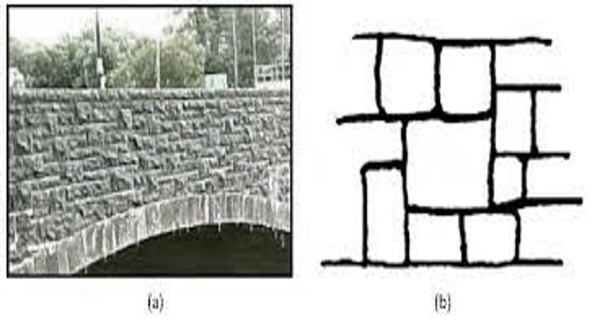
Masonry bridges are built with stone, brick, or concrete arranged in a particular design and mortared together. The design of masonry bridges includes two crucial steps: calculating the loads the bridge will have to support and building the masonry components to withstand those pressures. Bridges made of masonry need more labor to construct and last for a shorter time than bridges made of steel or concrete, but they are often less expensive to construct.
BUILDING BRIDGE USING GEOMETRY
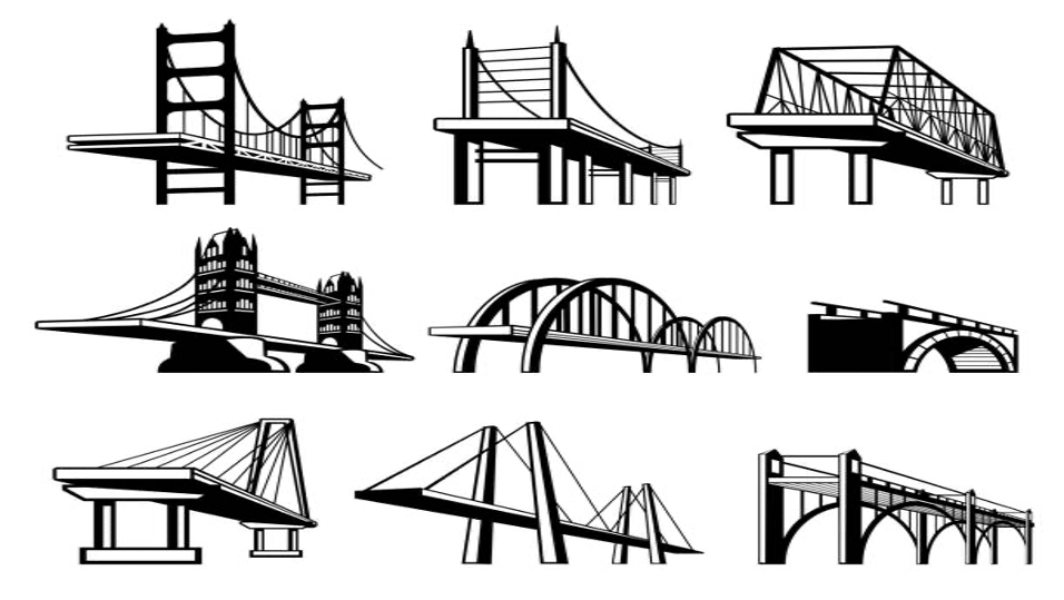
The loads that the bridge must support and the physical properties of the materials used to construct the bridge determine the form and shape of the bridge structure. The geometry needs to be carefully taken into account when designing bridges. The beams and columns, among other structural components, are constructed to be sturdy and practical by calculating loads to determine their size and strength. Aligning the bridge while accounting for its gradient, curvature, vertical clearance, and horizontal clearance; The final element is the analysis of bridge stability, which use geometric concepts to assess a bridge’s stability and confirm its safety under various load circumstances. For instance, the forces acting on a bridge may be calculated using geometry principles to see if it is at risk of collapse (Xanthakos, 1994). Depending on the unique requirements of the bridge and the environment in which it will be positioned, a variety of topologies can be utilized in bridge design. Typical geometrically-based bridge topologies include the following:
Beam Bridges/supported bridges
The most prevalent type of bridge construction in the UK is beam bridges due to their simple design. Beam bridge construction is comparatively easy and inexpensive. They consist of a horizontal beam that has piers or abutments at each end to support it.
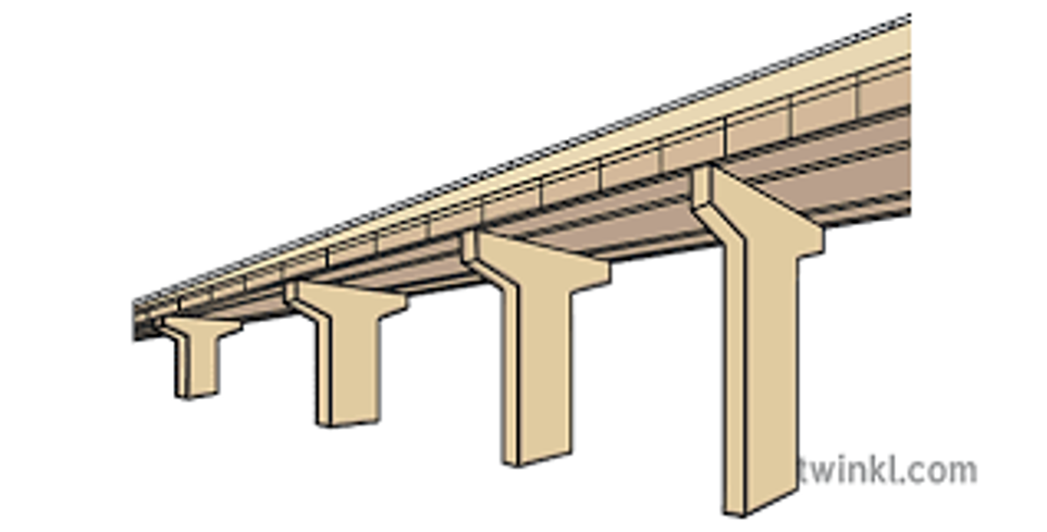
The beam bridges shown above can be built from various materials, including concrete, steel, and wood, and are often used for short spans, up to around 100 feet(Harper, 2022). Piers or abutments support a beam bridge at either end, and the beam is typically made of steel, concrete, or wood. The beam distributes the weight of the bridge to the terminal supports. To transfer loads from the beam to the ground, the piers or abutments are made of concrete or masonry(Newmark, 1949). It is common practice to utilize beam bridges to cross roadways, streams, and other small bodies of water. On somewhat flat terrain, they perform best. They may be seen in parks and other recreational locations and are frequently utilized as pedestrian bridges.
Integral beam bridges
Integral beam bridges are an alternative to conventional beam bridges with expansion joints and bearings. It stands out due to an integrated beam, a structural element that spans the aperture and supports the road or walkway(Harper, 2022). Typically, the integrated beam is made of reinforced concrete and cast in one piece. Maintenance issues with bridge bearings and expansion joints have been eliminated thanks to improvements in construction methods and prefabricated beam design.
An integral bridge beam’s substructure and superstructure function as one structural unit for short to medium-span bridges. Integral beam bridges have the major benefit of being easily and rapidly constructed utilizing prefabricated components. The remainder of the bridge is erected using prefabricated components, such as deck panels and parapets, while the integrated beam is often cast on-site using forms. This lessens the need for manufacturing on-site and speeds up construction. They are frequently used for automobile and pedestrian bridges and are ideally suited for medium to large spans, up to around 250 feet(Hambly, 1997). They are exceptionally well suited for urban settings since they can be built fast and effectively with little interference from traffic.
Cantilever bridges
Cantilevers are beams that extend outward from central support and are frequently used to support cantilever bridges. The cantilevers, fastened at either end, can support the bridge’s road or walkway because they are perfect for medium to large spans, up to around 1,000 feet(Harper, 2022). Cantilever bridges are widely utilized to cross rivers and other bodies of water. They differ from other structures by using balanced cantilevers, which are pairs of cantilevers that extend outward from the opposing sides of the central support and are anchored at either end. The highway or walkway of the bridge hangs between the two cantilevers. At the ends of cantilever bridges, commonly composed of steel or concrete, piers or abutments support the cantilevers(Science Direct, n.d). The illustration below demonstrates how hangers or cables support the bridge’s roadway or walkway, which hangs below the cantilevers. Trains, automobiles, and people may all cross this sort of bridge.

Cantilevers may bridge a canal without dividing it with river piers, which is particularly advantageous. The river channel is not obstructed, boat traffic may pass beneath the bridge, and there is less likely that the bridge would collapse during a flood emergency.
Arch bridges
By using an arch, a curved structure, they can support the bridge’s weight and the load it carries to the abutments at each end. Arch bridges may be built from various materials, including concrete, steel, and masonry, as seen in the figure below. They are beneficial for crossing gorges or valleys.
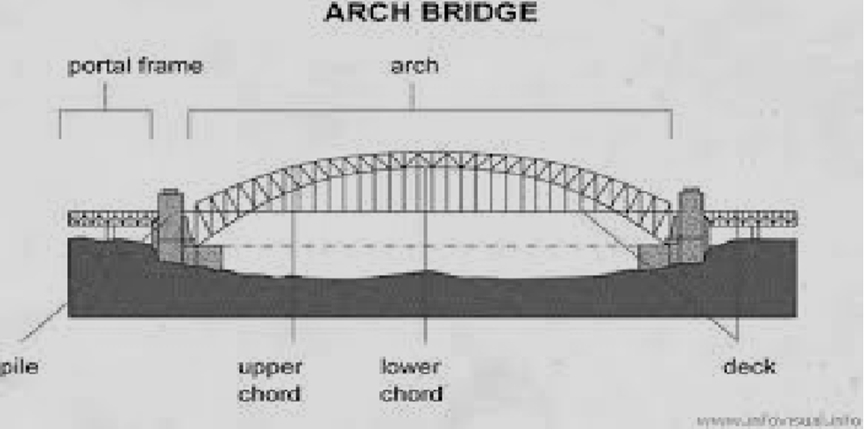
Abutments at each end of an arch bridge are designed like curving arches. The bridge’s semi-circular framework functions by shifting its weights onto the two abutments. The effects of tension on the underside of the arch are significantly reduced by the natural curve of the arch and its capacity to spread the strain outward (Harper, Steve., 2022). An arch bridge’s arch is often made out of discrete stones or blocks that are skillfully assembled and held in place by gravity. The bridge’s load and weight may be moved by the arch to the abutments at each end, where they are subsequently moved to the earth.
Arch bridges are often utilized for medium- to long-distance spans, up to around 500 feet. They are appropriate for various scenarios, including places with heavy traffic and unfavorable weather. They are visually appealing and may enhance a region’s aesthetic value. The limitations of this type of bridge construction include its small spans and protracted construction process.
Cable-stayed bridges
The term “cable-stayed” refers to a bridge whose pedestrian or vehicular walkway is supported by cables that are physically attached to towers. The cables secured at the top of the towers support the roadway or walkway suspended below. A cable-stayed bridge cannot be used if its tower or pylon load-bearing component is missing. Cables link the pylons to the deck beneath. They are widely used as an alternative to suspension bridges and are appropriate for medium to large spans up to 1,000 feet(Harper, 2022).
They are reachable directly from the tower’s summit or various locations down the column. They differ from other bridges because they employ fewer cables attached to a single tower or a group of towers rather than the bridge’s ends. The towers and cables of cable-stayed bridges, usually built of steel or concrete, are intended to withstand the bridge’s weight and the load it carries(Troitsky, 1997). The bridge design is shown in the image below.

The road or walkway hangs below the wires and is supported by hangers or other structural elements. One of the main issues with the bridge is that the central connection of the cables may put horizontal stress on the deck. To withstand constant stresses, the deck structure must be reinforced.
BRIDGE DESIGN AND CONSTRUCTION
Using Load and Resistance Factor Design (LRFD) and Load and Resistance Factor Rating (LRFR)
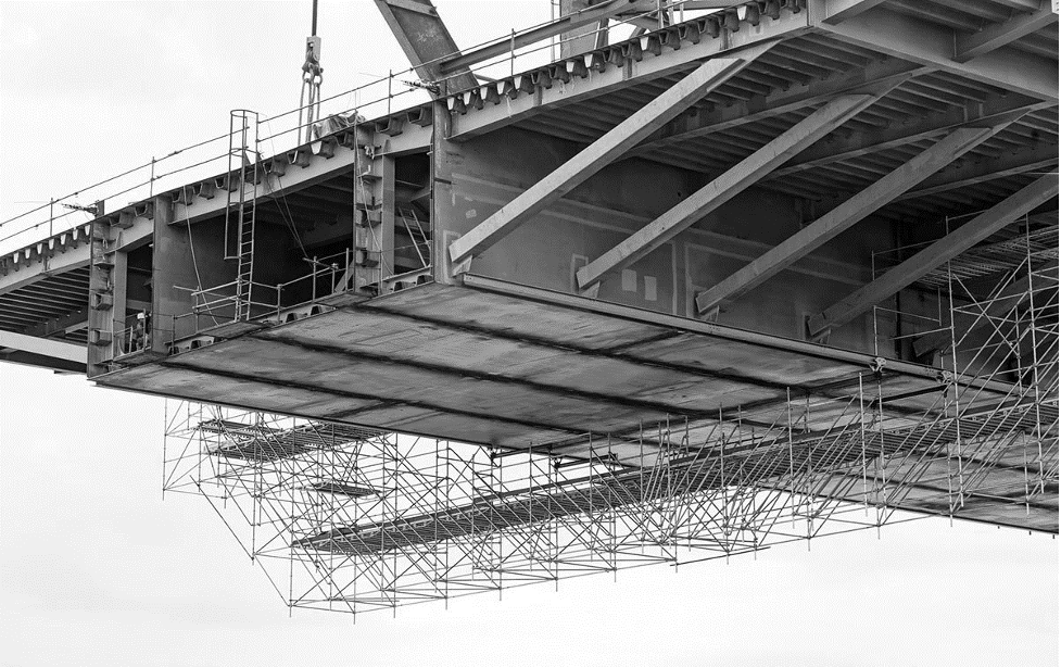
The process of designing a bridge is complicated and crucial, involving a variety of skills and considerations. To ensure the safety and integrity of the completed project, it is a crucial stage in the building process that has to be correctly planned and carried out. Site preparation, foundation building, structural steel, concrete work, and installation of any mechanical or electrical systems are just a few of the tasks involved in building a bridge. Bridge design determines a bridge’s structural soundness, load-carrying capability, functional needs, and aesthetic appeal(Wahis, 1990). Since a bridge’s design defines how it will be built, the two fields are closely intertwined. The design must consider the materials and construction methods used, as well as the regional climate and site conditions. The construction procedure must also follow the design plans to ensure that the bridge is constructed in line with the appropriate specifications and meets all safety and performance criteria.
The design and assessment procedures of load and resistance factor design (LRFD) and load and resistance factor rating (LRFR) have superseded or provided alternatives to other older approaches. In the design and assessment of bridges and other structures, LRFR and LRFD are both often employed. They are constructed to offer a high degree of trust in the security and effectiveness of the buildings they are used to design or assess, and they are founded on a solid scientific foundation. To guarantee the structural integrity and safety of the bridge, load and resistance factor design (LRFD) and load and resistance factor rating (LRFR) are used in the design and construction of bridges(Fu, 2013).
LRFD is used to determine the necessary strength of the various structural components of the bridge, such as the beams, columns, and foundations, during the design phase of a bridge project. This is accomplished by considering the estimated loads the bridge will support and the risks and other elements that impact how effectively it performs. To produce comprehensive blueprints and models of the bridge, the design process may entail using computer-aided design (CAD) software and other technologies.
The selection and use of the bridge’s building materials and techniques throughout construction must be per the LRFD design plans(Ghosn, 2011). This might involve using prefabricated parts, such as prefabricated steel or concrete beams, or conventional building methods, including using formwork and rebar. Throughout the building phase, there will be several inspections and tests to ensure that the bridge is being built in line with the design plans. After construction is complete, LRFR may be used to gauge the bridge’s structural soundness and predict how long it will be in use. To do this, the actual loads and stresses acting on the structure must be assessed and contrasted with the design values produced by the LRFD method. Based on this research, engineers may decide what repairs or enhancements are necessary to preserve the performance and safety of the bridge.
CONCLUSION
Engineering principles, materials science, and construction techniques are all used to create a bridge. The sizes, shapes, and forces acting on the bridge and the sizes, shapes, and forces acting on the various structural components are all determined by geometry in this process. The bridge designs under geometry are the beam bridges, a simple, cost-effective, and application-specific choice for short-span bridges; the integrated beam bridges are a practical and cost-effective solution for medium-span bridges and are appropriate for various applications. Similarly, cantilever bridges are a reliable and durable type of bridge widely used to span rivers and other bodies of water. They work well in applications with a medium to long span. Arch bridges, on the other hand, are a strong and durable type of bridge that is useful in various situations and applications. The last form of bridge discussed is the cable-stayed bridge. This robust and long-lasting design works well for applications requiring medium to large spans and is frequently employed as an alternative to suspension bridges.
Several engineering specialties, including structural engineering, geotechnical engineering, and materials science, are used in the design of bridges. To calculate the forces operating on the bridge and to establish the size and shape of the structural parts, geometry is an essential component in the design of a bridge. This helps to guarantee that the bridge is sturdy, durable, and can safely withstand the weights it will be subjected to. Every bridge has unique design, construction, and maintenance challenges. The designer must pick the best methods and accuracy to create each bridge individually.
References
Harper, S.(2022). “What Are the Five Main Bridge Designs?” ECL Civil Engineering, https://www.eclcivils.co.uk/what-are-the-five-main-bridge-designs/.
Balasubramanian, A. (2017). Bridges and their Types. Technical Report. The University of Mysore.
Pipinato,Alessio (2016). It helps to know the type of materials, compare them and explain them—the first edition. Waltham, MA: Elsevier.
Chatterjee, S. (2008). The design of modern steel bridges. John Wiley & Sons.
Newmark, N. M. (1949). Design of I-beam bridges. Transactions of the American Society of Civil Engineers, 114(1), 997–1022.
Hambly, E. C. (1997, February). INTEGRAL BRIDGES. In Proceedings of the Institution of Civil Engineers-Transport (Vol. 123, No. 1, pp. 30–38). Thomas Telford-ICE Virtual Library.
Cantilever Bridges – an overview | ScienceDirect Topics. (n.d.). Retrieved December 21, 2022, from https://www.sciencedirect.com/topics/engineering/cantilever-bridges
Troitsky, M. S. (1977). Cable-stayed bridges. Theory and design (No. Monograph).
Wahls, H. E. (1990). Design and construction of bridge approaches (Vol. 159). Transportation Research Board.
Fu, G. (2013). Bridge Design and Evaluation: LRFD and LRFR. 1.3 Bridge Construction and Its Relation to design. 1st edn. Wiley.
Ghosn, M., Sivakumar, B., & Miao, F. (2011). Load and resistance factor rating (LRFR) in NYS: volume I final report (No. C-06-13). The City University of New York. City College. Dept. of Civil Engineering.
Xanthakos, P. P. (1994). Theory and design of bridges. John Wiley & Sons.
 write
write