Introduction
The Critical Design Review (CDR), which signifies the passage from the preliminary design stage to the completion of the flying version of the spacecraft or subsystem, is a significant turning point in the spacecraft design process. The Preliminary Design Review (PDR) differences must all be resolved for the design to be ready for construction, which is the goal of the CDR(Schwartz et al., 2020). This evaluation is crucial because it establishes whether the spacecraft or subsystem can move on to the flight model phase or if it needs to be improved
In the CDR, each design document is carefully examined, including the Mechanical Design and Interface Description (MDID), the Failure Modes and Effects Analysis (FMEA), the Review Item Discrepancies (RIDs), and the Mechanical Model Drawings (MM). Together, these documents offer a thorough understanding of the mechanical features of the spaceship or subsystem design. The CDR also calls for the submission of all part approval documents (PADs) and inspection reports for the hardware of the current model, guaranteeing that every component complies with the requirements.
Document Delivery List (DDL)
A project management document called the DDL lists all the documents submitted for the CDR and their current state. Each document’s identification and issue numbers, appropriate annotations, and anticipated release date are recorded. The DDL for the CDR is shown in Table 1, with each document’s status and delivery dates highlighted.
| Document ID | Document Title | Issue No. | Current Status |
| 1 | Document Delivery List (DDL) | 1 | Submitted |
| 2 | Mechanical Design and Interface Description (MDID) | 1 | Submitted |
| 3 | Failure Modes and Effects Analysis (FMEA) | 1 | Submitted |
| 4 | Review Item Discrepancies (RID) | 1 | Submitted |
| 5 | Mechanical Model Drawings (MM) | 1 | Submitted |
Table 1
Mechanical Design and Interface Description (MDID)
The number one mirror, secondary replicate, light baffle, and every other interior additive, as well as the substances and qualities used to create them, must be described in the MDID. It should include explanations of the bodily and functional components and any supporting arguments (Liu et al., 2020). It should also consist of records on the interfaces that join the deployable components to the telescope’s shape and the structural additives to its structural elements.
The MDID must consist of a complete mass up to a maximum of two kg, with a 15% margin for the mass price range. The mass margin estimate needs to be additionally offered to support the selected mass budget.
Failure Modes and Effects Analysis (FMEA)
The FMEA, which identifies probable failure modes and assesses them consistent with their probability and severity, is crucial to the CDR. Risks related to the mechanical design may be systematically recognized with the use of the FMEA template protected with the mission. A sample FMEA desk, proven in Table 2, lists several failure scenarios, their chance, severity, and suitable mitigation measures.
| Failure Mode ID | Failure Mode Description | Likelihood | Severity | Mitigation Strategy |
| 1 | Structural Component Failure | High | Catastrophic | Redundancy in critical components |
| 2 | Deployment Mechanism Failure | Medium | Major | Thorough testing and redundancy |
| 3 | Mirror Misalignment | Low | Minor | Precision alignment and calibration |
| 4 | Light Baffle Damage | Medium | Moderate | Reinforcement of baffle structure |
| 5 | Thermal Stress | Medium | Major | Thermal protection and insulation |
| 6 | Interface Failure | Low | Minor | Rigorous interface testing |
| 7 | Material Degradation | Low | Moderate | Use of high-quality materials |
| 8 | Vibration Damage | Medium | Moderate | Vibration isolation mechanisms |
| 9 | Electrical Failure | Low | Major | Redundancy in critical electrical systems |
| 10 | Contamination | Medium | Minor | Proper cleaning and contamination control |
Table 2
Mechanical Model Drawings (MM)
The gadget structure’s trendy configuration drawings with the number one and secondary mirrors stowed and deployed are blanketed inside the MM phase. The telescope’s light baffle and different interior components must also be mentioned. Although the deployment mechanisms do not need to be used, they should have enough Mass and area to resemble an actual gadget.
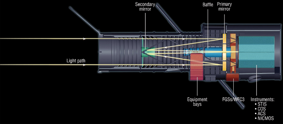
Figure 1
Figure 1 presents a simplified mechanical model drawing of the telescope instrument design, showcasing the primary and secondary mirrors, light baffle, and telescope support structure.
The MM has labels and annotations to enhance comprehension and readability. Each mechanical shape is recognized using these labels, which connect them to the relevant Bill of Materials (BOM) entries. The reviewers can recognize the materials utilized, quantities, and suppliers for every aspect by move-referencing the MM with the BOM and demonstrating the design’s crowning glory and readiness for production.
The MM is generally displayed visually, consisting of 3D models or Computer-Aided Design (CAD) drawings. These graphical representations are beneficial for evaluation purposes and serve as crucial reference materials for later levels of the development of the spacecraft or subsystem. Additionally, by proving that the designer independently constructed the mechanical model, the submission’s inclusion of SolidWorks elements and meeting documents strengthens the layout’s openness and originality.
Finally, the Mechanical Model Drawings (MM) part gives an essential visual representation of the mechanical layout of the spaceship or element. The MM depicts the configuration of additives, deployment strategies, and other internal features via in-intensity drawings and diagrams. The Bill of Materials (BOM) move-reference inside the MM improves the reviewers’ comprehension of the physical characteristics of the layout and its readiness for creation. The MM, a critical factor of the CDR, helps make the layout overview system more cohesive and effective by verifying that the spacecraft or subsystem is on course to finish its task successfully and reliably.
The table below shows a Sample Bill of Materials (BOM)
| Part ID | Part Description | Material | Quantity |
| 1 | Telescope Support Frame | Aluminum Alloy | 1 |
| 2 | Primary Mirror | Glass | 1 |
| 3 | Secondary Mirror | Glass | 1 |
| 4 | Light Baffle | Aluminum | 1 |
| 5 | Electronic Components | Various | 10 |
| 6 | Deployment Mechanism | Steel | 2 |
Mass Budget
A critical thing of the CDR is the Mass Budget, which ensures that the Mass of the spaceship or subsystem adheres to the mounted restrictions. It also has a sufficient margin to account for unanticipated situations. A pattern mass budget is shown in Table 3, which also calculates the general Mass while accounting for the chosen margin.
| Component | Mass (kg) | Margin (%) | Total Mass (kg) |
| Telescope Support Frame | 0.8 | 10 | 0.88 |
| Primary Mirror | 0.3 | 10 | 0.33 |
| Secondary Mirror | 0.2 | 10 | 0.22 |
| Light Baffle | 0.1 | 10 | 0.11 |
| Electronic Components | 0.2 | 10 | 0.22 |
| Deployment Mechanism | 0.4 | 10 | 0.44 |
| Total | 2 | 10 | 2.2 |
Table 3
Conclusion
Ultimately, the Critical Design Review (CDR) is vital to ensuring that the spacecraft or subsystem is prepared for development and eventual launch. The CDR certifies that each discrepancy has been resolved and that the design complies with all necessities through the thorough overview and submission of several documents, such as the Mechanical Design and Interface Description (MDID), Failure Modes and Effects Analysis (FMEA), Review Item Discrepancies (RIDs), and Mechanical Model Drawings (MM). The CDR’s successful completion improves the design’s average coherence and readiness, giving the investment organization and launch issuer more warranty that the venture might be dependable and a success.
The CDR presents a clear and succinct description of the spacecraft or subsystem’s mechanical elements via figures and tables, facilitating effective verbal exchange and assessment by means of stakeholders and reviewers. The primary and secondary mirrors, light baffle, and telescope assist systems are all depicted in detail within the Mechanical Model Drawings (MM), even as the mass contribution of every factor is broken down in the Bill of Materials (BOM).
Additionally, the Failure Modes and Effects Analysis (FMEA) suggests suitable techniques for mitigating risks related to the mechanical layout. The mass finance guarantees that the layout complies with weight restrictions while considering a protection buffer.
The designers’ capability to deliver a well-engineered design answer, successfully represented using SolidWorks, and effectively manipulate mechanical dangers is confirmed via the CDR’s hit completion. The CDR indicates the designers’ dedication to ongoing improvement and rigorous attention to elements in the design system by integrating suggestions and solving issues from the Preliminary Design Review (PDR) (Al-Hammadi et al., 2022). As a result, the CDR prepares the spacecraft or subsystem for progression to the flight model phase, opening the door for a destiny assignment to achieve success and reliability.
References
Schwartz, N., Brzozowski, W., Milanova, M., Morris, K., Todd, S., Ali, Z., … & MacLeod, D. (2020, December). High-resolution deployable CubeSat prototype. In Space Telescopes and Instrumentation 2020: Optical, Infrared, and Millimeter Wave (Vol. 11443, pp. 565–577). SPIE.
Liu, X., Deng, J., Li, K. F., Jin, M., Tang, Y., Zhang, X., … & Li, G. (2020). An optical telescope with Cassegrain metasurfaces. Nanophotonics, 9(10), 3263-3269.
Levinson, Z. A., & Smith, B. W. (2020, March). Lithographic pattern formation in the presence of aberrations in anamorphic optical systems. In Extreme Ultraviolet (EUV) Lithography XI (Vol. 11323, pp. 36–47). SPIE.
Beish, J. D. Cassegrain Telescopes for Amateurs.
Autieri, C., & Sanyal, B. (2019). A Theoretical Overview of the Quantum Phenomena at Oxide Interfaces: The Role of Spin and Charge. Oxide Spintronics, 107.
Stott, P. (2019). Historical plant geography: an introduction. Routledge.
Al-Hammadi, A. S. S., Saidin, S., & Ramlee, M. H. (2022). Simulation Analyses Related to Human Bone Scaffold: Utilisation of Solidworks® Software in 3D Modelling and Mechanical Simulation Analyses. Journal of Human Centered Technology, 1(2), 97–104.
 write
write