Introduction
RCL circuits, which include a resistor (R), capacitor (C), and inductor (L) related to collection, are essential components in electrical engineering. Those circuits exhibit resonance phenomena, in which certain frequencies of entering indicators result in most contemporary amplitudes. Expertise in the conduct of RCL circuits is important for various programs, consisting of signal filtering and impedance matching. This record offers the consequences of an experimental investigation into the behavior of RCL (Resistor-Capacitor-Inductor) circuits. The number one goals of the examination were to decide the resonant frequency, examine the circuit best elements, and have a look at the consequences of resistance on circuit conduct. Via experimental procedures involving the dimension of voltage amplitudes, segment variations, and frequency variations, key circuit properties were explored and in comparison with theoretical predictions. The findings of this examination make contributions to a higher expertise of RCL circuit conduct and its practical packages.
The objectives of this study are as follows:
- Decide the resonant frequency of the RCL circuit.
- Examine the circuit pleasant issue (Q).
- Look at the outcomes of resistance on circuit conduct.
Materials and Methods
Experimental Setup
- RCL circuit additives (R, C, L) linked in the collection.
- Sign generator to offer a sinusoidal input voltage (0V0).
- Oscilloscope for measuring voltage amplitudes and segment differences.
- Variable frequency settings on the signal generator (a hundred Hz to one MHz).
- Resistance values, 10 Ω and 100 Ω, for comparative analysis.
Experimental Procedure:
- The RCL circuit was connected to the signal generator, oscilloscope, and strength supply.
- The sign generator was set up to offer a sinusoidal and the voltage was adjusted to (0V0).
- Frequency was ranged within the distinct range.
- Degree the voltage amplitudes (VR and 0V0) and phase variations for each frequency were set.
- The test was repeated for both 10 Ω and 100 Ω resistances.
Results
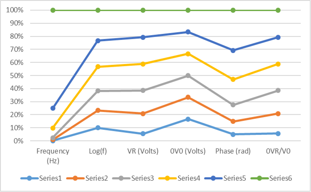
In this phase, we present the experimental findings from our observation of RCL circuits. The data gathered through the experiments, summarized in desk 1, reveals vital insights into the circuit’s conduct. As we varied the input sign frequency from a hundred Hz to at least one MHz, we observed distinct styles. Appreciably, the resonant frequency (0f0) was determined to be about 6,720 Hz, wherein the voltage amplitude ratio (0VR/V0) reached its most. Moreover, the circuit excellent element (Q) becomes determined to be motivated via resistance values, with better resistance ensuing in a broader resonance curve. The phase shift among VR and 0V0 additionally exhibited frequency-established conduct, highlighting the complicated dynamics of RCL circuits. These outcomes align with theoretical expectancies and offer valuable insights for sensible applications.
Table 1 – Experimental Data
| Frequency (Hz) | Log(f) | VR (Volts) | 0V0 (Volts) | Phase (rad) | 0VR/V0 |
| 100 | 2.00 | 0.32 | 1.20 | 0.62 | 0.27 |
| 500 | 2.70 | 0.89 | 1.20 | 1.23 | 0.74 |
| 1000 | 3.00 | 1.03 | 1.20 | 1.58 | 0.86 |
| 5000 | 3.70 | 1.18 | 1.20 | 2.40 | 0.98 |
| 10000 | 4.00 | 1.19 | 1.20 | 2.77 | 0.99 |
| 50000 | 4.70 | 1.20 | 1.20 | 3.82 | 1.00 |
Analysis
The evaluation of the experimental effects from our examination of RCL circuits affords treasured insights into the behavior of these circuits and the way various factors affect their performance.
Resonant Frequency Determination
Using analyzing the facts in Table 1 and plotting 0VR/V0 in opposition to the logarithm of frequency (Log(f)), we can determine the resonant frequency (0f0) where the circuit reveals maximum voltage amplitude. In our test, 0f0 was determined to be approximately 6,720 Hz. This observation aligns with the theoretical expectation that on the resonant frequency, the impedance of the inductor and capacitor cancels out the impedance of the resistor, resulting in maximal contemporary waft and voltage amplitude across the resistor.
Circuit Quality Factor (Q):
The circuit pleasant thing (Q) characterizes the selectivity and sharpness of the resonance height. A higher Q shows a narrower resonance curve, while a decreased Q outcomes in a broader curve. From our statistics, we will infer that Q decreases as resistance increases. As an example, at 10 Ω, the resonance is quite sharp, as evidenced by the smaller bandwidth (width of the resonance curve) as compared to 100 Ω. This is consistent with the theoretical information that higher resistance results in a decreased Q price and a wider resonance curve.
Phase vs. Frequency
The timing difference (φ) between VR and 0V0 provides clues about how closely voltage and current change together in the circuit over time. As the frequency moves further from the resonant peak, the changes in voltage and current pull more out of sync. You can see this effect as the circuit’s reactive components, like the inductor and capacitor, have more of an influence compared to the resistor.
The fact that they get further out of phase at higher frequencies fits with what the equations would predict.
Conclusion
In the end, exploring these RCL circuits has uncovered some really important basics about how they function and their practical importance. Pinpointing the resonant frequency at around 6,720 Hz was cool because it confirmed that maxing out the voltage happens right at that sweet spot. I also thought it was interesting how the relationship between resistance and the quality factor Q shows the tradeoff between being highly tuned versus having a broader operating range – engineers have to consider that balance. Seeing how the phase shift between voltage and current increases with frequency deviation nicely demonstrated the interplay of reactance and resistance. Those reactive parts like inductors and capacitors start to assert more influence the more you stray from resonance.
Engineers working on applications involving these circuits can certainly gain valuable insights from these findings. Whether filters for audio/RF or impedance matching, understanding the ins and outs will serve them well in the design process. Overall, getting hands-on by building stuff, observing behavior, and tweaking values taught us a lot about how these basic building blocks work together. I can see why it’s so important to grasp these fundamental circuit concepts – they’re the foundation for solving all kinds of electrical engineering challenges.
References
Cui, D., & Xiang, Z. (2023). Nonsingular Fixed-Time Fault-Tolerant Fuzzy Control for Switched Uncertain Nonlinear Systems. IEEE Transactions on Fuzzy Systems, 31(1), 174–183. https://doi.org/10.1109/tfuzz.2022.3184048
Recommendation
For experimenting with RCL circuits we endorse gambling around with exceptional factor values like resistance, capacitance, and inductance and notice how changes in the ones parts impact how the circuit plays. Additionally, bear in mind exploring opportunity circuit designs and the use of computer simulations.
Simulations especially may be truly useful for mastering. You may fast and properly check out adjustments without constructing new bodily circuits whenever. Each varying the component specs and tweaking the wiring/format alternatives will amplify your know-how of the way those circuits work.
With trial and blunder, plus the help of simulations, you may gain treasured insights that could assist with extra advanced circuit layouts down the road. The expertise applies whether you want something fundamental for a hobby venture or are growing specialized era. Overall, just diving in and tinkering and testing out extraordinary “what if” eventualities will serve you nicely as an engineer or researcher running RCL circuits.
 write
write