Introduction
In the electricity transmission and distribution business, FACTS devices are a revolution. The FACTS devices regulate a variety of essential parameters of an electrical energy signal at a rapid rate with minimal mechanical effort [1]. When the other series of shunt-linked FACTS devices add novel dynamic regulations to the power systems, their inclusion in the electrical power transmission system has substantially impacted the performance of classical distance schemes. STATCOM, a shunt-connected FACTS system, and its mathematical technique are described in this work.
Advantages of STATCOM
Unlike SVC, STATCOM (Static Synchronous Compensator) is an upgraded FACTS device that does not need a physical inductor or capacitor to sustain reactive power [1]. STATCOM provides reactive power by transferring instantaneous reactive power between AC system phases. Similarly to a synchronous condenser, the regulated output voltage is kept in step with the line voltage and may be adjusted to draw between capacitive or capacitive current from the line. The transmission grid is shunt linked to the STATCOM system. The STATCOM has voltage transformers (VTs) that measure the grid voltage.
The Advanced Digital Control (ADC) receives the voltage waveform from the VT input and regulates the different sub-modules to create one of two voltage waveforms [2]: When there are no power system issues, the STATCOM acts as an inductive device, absorbing responsive power from the grid; when there are grid issues, the STATCOM acts as a capacitive device, producing reactive power to the grid; when there are grid issues, the STATCOM acts as an inductive device, absorbing reactive electricity from the system; when there are grid issues, the STATCOM acts as a capacitive device, producing reactive power to the grid; when there are grid issues, the ST Finally, the STATCOM maintains grid stability by continuously monitoring grid voltage and adjusting its reaction power output in reaction to system disruptions.
Power flow in STATCOM
The voltage from the operating power (HV) bus is reduced by a transformer (TR) so that reduced power rating valves (S1-S6) can be used [3]. It features a capacitor at the dc-link to create a current route. To lower the harmonic components in voltage, a smoothing reactor/transformer is utilized. STATCOM has a response time of 15-30 milliseconds, which is among the fastest FACTS devices. The main reasons for its quick reaction are the elimination of any rotating motion and the use of IGBTs, IGCTs, or GTOs as power switches [3]. This is where the name STATic synchronous COMpensator comes from (STATCOM). The principal STATCOM controller in a balanced electrical system comprises an internal current circuit and an outside control loop.
Multi-pulse converters and multilevel converters are the two major kinds of STATCOM main switchboard configurations. Three-phase bridges are linked in parallel on the DC side of a multi-pulse translator. The spans are magnetically connected through a zigzag generator, commonly configured so that the bridges look in series when seen from the AC side. Each transformer winding is phase-shifted to remove chosen harmonics and provide a multi-pulse output voltage. Pulse Width Modulation (PWM) can be used to increase harmonic content at the cost of increased switching and snubber loss and a lower fundamental Var rate [2]. The downsides of a multi-pulse converter architecture are that the phase-shift transformers make the process complex and heavy, and each STATCOM installation will have its transformer design.
Types of STATCOM
Inverters are more versatile and have a wider use than multi-pulse converter-based STATCOM. They can be used to handle imbalanced loads and as active power filters. This layout does not require a phase shift transformer, reducing investment costs and lesser power loss. The three types of multilevel converter setups are phototransistors, flying capacitors, and cascade converters.[3]
In addition, the controller has been tweaked to account for the effects of various coupling transformer configurations. A neutral current controller is designed for STATCOM functioning in unbalanced electrical systems, leveraging the Fortes cue decomposition approach to get sequence components [4]. Without using a 2nd spectral notch filter, the segregation of desirable and undesirable sequence components is demonstrated. Following that, a supplemental controller for load compensation is created, which comprises voltage control and inverse sequence load current compensation. In asymmetric failures, a transitory overvoltage (TOV) controller is also being developed[4]. A power balancing controller and a voltage regulator are created and block schematics of entire controllers.
The OMFDS (Operation Monitoring and Fault Diagnosis System)
The OMFDS (Operation Monitoring and Fault Diagnosis System) is a critical component of the STATCOM installation that has received insufficient attention [2]. Real-time supervision, fault alerting, post-fault analysis, and a consumer Human Machine Interface are all provided by OMFDS (HMI). It serves as the STATCOM’s information centre, collecting and storing data from all subsystems and determining if the STATCOM is operational [2]. The analysis findings are presented to clients through HMI, and authorized remote OMFDS can access them over a Local Area Network or the Internet.
As for switching devices, STATCOM uses IGBT, IGCT, or GTO. Both are flipping ON, and flipping OFF events may be regulated in these switches. As a result, compared to the one degree of flexibility provided by thyristors in SVCs, this provides two degrees of freedom. This allows it to be controlled more quickly and efficiently.
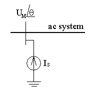
STATCOM’s mathematical model is depicted in the diagram above [3].
Application of STATCOM
STATCOM’s primary application offers reactive current compensation and keeps the voltage on the connected bus within safe limits [4]. STATCOM has been used in the mining and metallurgical sectors to improve their electricity supply. Because petrochemical companies employ high-capacity motors, the voltage on the feeder drops. The utility has deployed three MVAr STATCOM units in British Columbia to ensure power reliability and offer timely dynamic voltage support under stable and unstable fault scenarios [3]. Gold mine facilities have employed the STATCOM system to help with high power requirements or increasing load owing to expansion mining facilities [2]. High-power electrical machinery must be fed over extremely long cable lengths for a new mining operation in Ontario. They utilized six STATCOM units, each rated at 4.5 MVAr, for reactive power supply and voltage regulation to aid their functioning [1]. STATCOM’s quick reaction time guarantees that power performance requirements are met and the lifetime of motors and manufacturing applications, resulting in a quick return on investment.
In conclusion, with the significant increase in electric power demand in recent years, the restoration of urban and distribution power networks has become increasingly necessary. During the transmission improvement process, there will be a high need for reactive power adjustment to improve the efficiency and reliability of AC transmission systems. The global electricity business has grown at a breakneck pace in the previous two decades. With fast development comes various issues in power systems, such as insufficient dependability, significant line losses, and poor power quality. FACTS devices, such as STATCOM, are critical to tackling these issues.
REFERENCES
[1] A. Augustine, E. Paul, R.D Prakash, B.M Balakrishna, & R. Xavier. (2016, March). Voltage regulation of STATCOM using fuzzy self tuning PI controller. In 2016 International Conference on Circuit, Power and Computing Technologies (ICCPCT) (pp. 1-7).
[2] N. Djagarov, Z. Grozde, G. Enchev, & J. Djagarova. (2019, May). Mathematical Model for Study of Low-Voltage Ride Through of Wind Permanent Magnet Synchronous Generator by means of STATCOM. In 2019 20th International Scientific Conference on Electric Power Engineering (EPE) (pp. 1-5).
[3] M. Murali, A. Gokhale, A. V Pandey, & E.Sharma. (2016, July). Modelling, design and comparison of PI and PID controllers for Static Synchronous Compensator (STATCOM). In 2016 IEEE 1st International Conference on Power Electronics, Intelligent Control and Energy Systems (ICPEICES) (pp. 1-6).
[4] P.Singh, & R. Tiwari. (2019). STATCOM model using holomorphic embedding. Access, 7, 33075-33086.
 write
write