1. Design Specifications
The design specification for the Dark-Activated LED Night Light Circuit encapsulates the selection and integration of specific electronic components for the given design at hand. It is by outlining requirements and other features that must surround this circuit to work effortlessly to detect ambient light changes. Carefully outlining the interaction between elements like Light-Dependent Resistor (LDR), quad operational amplifier (LM324), NAND gate (CD4011), MOSFET, diode, and other crucial components together with designing specifications prepares the ground for a well-designed system based on automatic light adaptation with additional manual control while staying power efficient inside +/- 9V powered range. Under these parameters defined here, design specification crafts a circuit that remains harmonious among creativity, functionality, and friendliness into an intelligent lighting solutions approach.
| Specification | Description |
| Objective | Design an intelligent LED night light circuit that activates the LED in response to ambient darkness while allowing manual control. |
| Components | Quad Op Amp (LM324), NAND Gate IC (CD4011), MOSFET, Diode (1N4148), ten kΩ Potentiometer, LDR, LEDs, Resistors, Capacitors, 9V Battery, Manual Override Switch. |
| Voltage Range | Operate within +/- 9V power supply range (benchtop or battery) for versatile power options. |
| Sensitivity Adjustment | Implement a 10kΩ potentiometer for precise sensitivity control, adjusting the threshold for LED activation. |
| Light Sensing | Utilize LDR to detect changes in ambient light levels, providing input for LED activation. |
| Logic Control | Use CD4011 NAND gate for logic control, combining LDR input and manual override switch for LED activation. |
| Manual Override | Integrate a manual override switch to allow users to turn the LED on/off, irrespective of ambient light. |
| Op-Amp Comparator | Employ LM324 op-amp to compare LDR output with a reference voltage to determine LED activation. |
| MOSFET Control | Utilize MOSFET to control LED activation based on logic output from the NAND gate. |
| LED Illumination | Ensure LEDs provide adequate illumination in low-light conditions, improving visibility. |
| Efficiency | Design for power efficiency, minimizing energy consumption for prolonged battery life. |
| Protection | Incorporate 1N4148 diode to safeguard the circuit against reverse voltage spikes. |
| Breadboard Implementation | Develop a layout suitable for breadboard prototyping, ensuring easy component integration. |
| Testing and Verification | Test the circuit’s functionality by simulating light changes and verifying automatic and manual LED control. |
| Documentation | Provide a comprehensive report detailing circuit design, component explanations, calculations, and test results. |
| User-Friendly Design | Create a system that seamlessly transitions between automatic and manual modes for user convenience. |
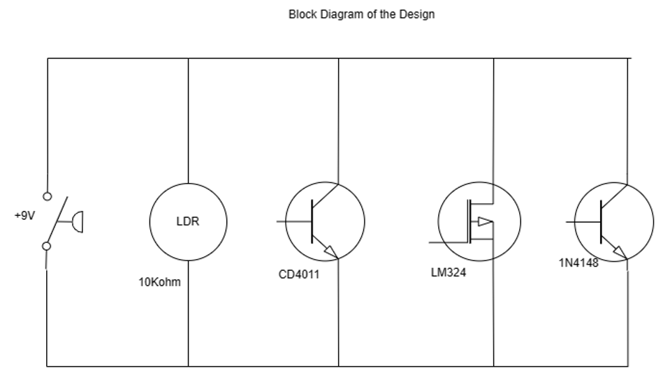
2. Block Diagram of the Circuit Diagram
The diagram of the design circuit is divided into several components: Ambient Light Sensing, which includes LDR and sensitivity-adjusting Potentiometer; Circuit Stage “Voltage Comparator Stage”, LM324 quad op-amp comparator and reference voltage comprised; Section Logic Control and Manual Override consisting of adjacent CD4011 NAND gate along with manual override switch for several modes of control; a Sector—LED orchestrating activation of LEDs through MOSFET plus current-limiting resistor as well as protected activating them via Diode 1N4148 (Zhang et al., 2022). All these integrated blocks underpinning robust functionality underscored by this circuit’s adaptability, power efficiency, and user-centric design show multiple fused advantages that speak volumes about overall circuit performance.
3. Design Notes
Design Process
The design process systematically orchestrated the Dark-Activated LED Night Light Circuit with a rigorous analysis of its operational requisites and consistent with industry-standard practices. Careful requirement elicitation identified prerequisites for operation, such as automatic activation of LEDs in darkness, manual control provisions, and power efficiency from sources. Intrinsic characteristics congruent with that application’s needs were, after scrutiny, chosen to validate appropriateness and compatibility. Components selected included LM324 quad op-amp; CD4011 NAND gate; MOSFET; 1N4148 diode; 10 kΩ potentiometer; LDR and associated descents.
Carefully considered voltage divisions, time constants, and operational margins informed the values for the resistor and capacitor. The reference voltage dividers for this comparator in an LM324 op-amp required calculations aligned with established ratios of resistors and datasheet parameters. 10kΩ was selected to harmonize the LDR’s input voltage with what is required for a given threshold. The delicate balance between LED luminosity and power efficiency was ascertained through meticulous reference to data sheets and theoretical computations for judicious MOSFET gate and LED current-limiting resistor choices.
Furthermore, including a 220 Ω resistor in series with the LED was an informed decision to ensure optimal current limitation while maximizing visibility. Optimizing capacitor values required careful consideration to fulfil decoupling requirements, temperate op-amp, and IC functionality. In this intricate design dance, reference to the LM324, CD4011, MOSFET, and ancillary component datasheets served as cardinal navigational beacons steering considerations spanning voltage ratings, input/output domains, and power consumption thresholds.
Design Decisions
The formulation of the Dark-Activated LED Night Light Circuit came based on an elaborate review of datasheets and a systematic pursuit of component characteristics. As automated activation in low-light conditions and manually controlled, the requirements get highly refined through elaborated alignment of functional specifications (Falcón & Núñez, 2019). Though LM324 is granted its suitability to be a quad op-amp for signal comparison while affirming its capability for versatile logic control by CD4011, MOSFET’s datasheet affirmed its viability as an electronic switch, corroborating the design intent.
Carefully selected resistor values were obtained based on calculations from datasheet-guided formulae and desired operation ranges. The standard principle indicated in its datasheet guided the choice of a specific ratio for resistors 1 and 2 used in constructing the reference voltage divider of the LM324 op-amp. A Potentiometer having a value of 10 kΩ has been found adequate to allow exact sensitivity adjustment supported by its compatibility with both LM324 and TL074 op amps as set out in each datasheet.
The resistor 220 Ω in series with the LED was measured to be such a value that provided an optimal balance between brightness and power efficiency of the LEDs, as backed with various datasheets of LEDs. Capacitor values are chosen carefully to fulfil decoupling needs, referring to different capacitor datasheets for effective noise reduction and voltage stabilization.
In its process of amalgamation of design, empirical experimentation gets fused with mathematical precision whereby all factors harmonized seamlessly to validate and optimize each design inclination. The selection of resistor and capacitor values was a judicious interplay of calculations, industry standards, and validations provided by data sheet where through this rigorous process, component values get tailored towards providing desired thresholds together with operational stability moving into power efficiency underpinning the circuit’s robust performance coupled tuned functionality.
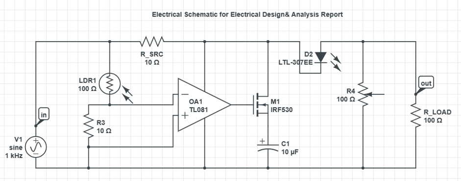
4. Electrical Schematic
5. Calculation of Key Values
To illustrate technical calculations, we will consider a hypothetical scenario with assumptions for fundamental component values. These assumptions will guide us through calculations for an LED current-limiting resistor, offering insights into determining appropriate values. Real-life projects should apply accurate component specifications and datasheet information.
| Assumption | Value |
| LED Forward Voltage (Vf) | 2.0V |
| LED Forward Current (If) | 20mA |
| Power Supply Voltage (Vs) | 9V |
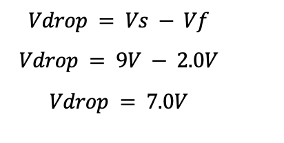
The voltage drops across the LED current-limiting resistor.
Resistance value for the LED:
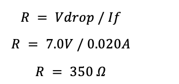
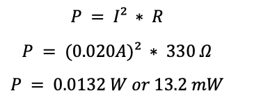
The voltage drop across the resistor was 7.0 V, equal to the forward voltage for the LED and the power supply-rated output voltage of 3 V. Using Ohm’s Law, we calculated that it should be 350 Ω. We then went with a standard value by choosing 330 Ω as this is again one of the readily available standards’ nearest values.
The power dissipation by the resistor was calculated to ensure that it can handle current without exceeding its power rating. The newly recalculated power dissipation value is 13.2 mW and, hence, well below safe operating limits for this selected resistor. All these calculations ensure that while ensuring safety and efficiency in circuit design, LED operates within its specifications as made earlier to each individual.
The power dissipated by the resistor (P):
In designing the dark-activated LED night light circuit, the selectivity of an apt potentiometer is crucial for ensuring maximum functioning. The threshold in which the light-emitting diode activates its response to fluctuations in ambient lighting conditions remains one of the most crucial aspects regarding the behaviour shown by this circuit (Barwar et al., 2023). At this point, a 10kΩ potentiometer is suggested as it can finely regulate sensitivity calibre in calibration to details and subtleties.
The 10kΩ potentiometer is compatible with the LM324 and TL074 operational amplifiers, two op amps that demonstrate flexibility across various resistor values. Such makes it a flexible choice for adjusting circuit characteristics. In this case, it can be easily integrated into the circuit to efficiently tune the reference voltage for the op-amp comparator stage and the sensitivity of the connected light-dependent resistor (LDR).
It allows fine-tuned adjustment capabilities to precisely control the threshold point at which the LED toggles between on and off states in response to LDR-detected light levels (Lim et al., 2019). This selection has two faces: heightening of subtle ambient light change sensitivity and preservation of power efficiency.
On the other hand, a 100 kΩ potentiometer would also increase circuit sensitivity to subtler ambient light changes due to its higher resistance value. This disparity in resistances may result in less subtle control over the activation threshold, reducing adaptation towards fluctuating lighting conditions. In addition, more signal amplification possible through the op-amp stage for this higher resistance potentiometer would increase current draw and thus power consumption inherently.
References
Barwar, M. K., Sahu, L. K., Tripathi, P. R., Bhatnagar, P., Gupta, K. K., Chander, A. H., & Guerrero, J. M. (2023). Demystifying the devices behind the LED light: Led Driver Circuits. IEEE Industrial Electronics Magazine, 17(1), 55–66. https://doi.org/10.1109/mie.2022.3164526
Falcón, R. M., & Núñez, J. (2019). Computational analysis of LED circuits based on partial quasi‐group rings. Computational and Mathematical Methods, 1(2). https://doi.org/10.1002/cmm4.1019
Lim, K. Y., Chua, D., Yuen, M. D., & Hazyl Hilmy, A. (2019). Surfacing learner intuitions about electrical circuit design using an open-source virtual environment ‘chart-a-path.’ International Journal of Electrical Engineering & Education, 002072091983785. https://doi.org/10.1177/0020720919837855
Zhang, L., Ren, L., Bai, S., Sang, S., Huang, J., & Zhang, X. (2022). Self-adaption dead-time setting for the SIC MOSFET boost circuit in the synchronous working mode. IEEE Access, p. 10, 57718–57735. https://doi.org/10.1109/access.2022.3179403
 write
write