Abstract
The goal of this work is to gain numerical physical insights into flow and heat transport properties. A non-uniform orthogonal staggered grid, as well as a finite difference technique which is a control-volume based one using a power-law scheme, are used to solve the governing equations. Computational fluid dynamics is used to solve the momentum equations’ velocity-pressure coupling. The Elliptical Pin Fin Heat Sink is made up of metallic plates with circular pins placed between them. The aim of this evaluation is to explore the consequences of different pin-fin arrangements. Plate fin heat sinks, on the other hand, have a lower unnaturally performance rating. Heat sink calculations based on the elliptical pin fin design and the results they produce.
Introduction.
Thermal management is becoming an increasingly important integrant of electronic product configuration as the heat dissipation of microelectronic devices increases and the overall form factors decrease. Electronic equipment’s component temperature has a negative impact on both its dependability and its lifespan. According to the relationship between silicon semi-conductor device reliability and operation temperature, Lower operating temperatures enhance dependability and life expectancy by an order of magnitude. As a result, maintaining the operating temperature of the device within the range specified by the device’s designers can help ensure extended component life and dependable operation.
The maximum functioning junction temperature of an electrical component impacts how well it may be used. Excess heat from the device must be transmitted to the environment in order for the component to reach an acceptable temperature. A heat sink is the most frequent way for dissipating heat from a component. For predicting a component’s junction temperature, the heat sink’s thermal resistance is an essential input. To determine this thermal resistance, you can utilize analytical or experimental methods.
An electric heat sink is a passive device that dissipates heat generated by a device into the environment. In computers, heat sinks are used to cool electrical components. Heat sinks are used to keep the temperatures of high-power semiconductor devices like power transistors and optoelectronic devices like lasers and light emitting diodes (LEDs) in check when the fundamental heat dissipation performance of device packages is insufficient.
CFD Modelling.
The study of getting numerical solutions to governing equations for fluid flow while moving the solution across space or time to construct a numerical representation of the entire flow field is known as computational fluid dynamics (CFD). Flows that are erratic, compressible or incompressible, viscid or viscous., as well as non-ideal and reactive fluid dynamics, may all be represented by the equation. The shape chosen is determined by the intended use. The intricacy of the geometry, the flow mechanics, and the computational time necessary to get a solution describe the state of the art.
We are utilizing fluent software in this study to model pressure drop and heat transport in a heat sink and then compare the results to actual experimental data [4, 5, 6]. Many CFD SOFTWARE solvers and turbulence models have been developed to forecast the impacts of shifting wind velocity on thermal resistance, heat flux, and Nusselt number.
CFD is a method of investigating fluid flow, heat transfer, and other processes using a computer-based simulation methodology and chemical processes, among other things. CFD is used in this dissertation to study the flow and heat transfer of fluids. CFD will be less expensive than traditional testing since the number of configurations that may be investigated is proportionate to the cost of the experiment, but CFD findings can be generated for virtually no extra expense. Experiments are substantially more expensive than parameterized equipment optimization studies using CFD.
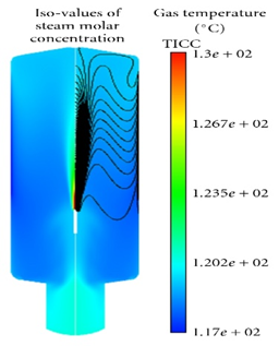
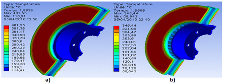
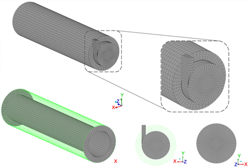
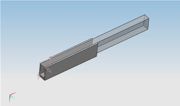
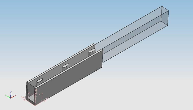
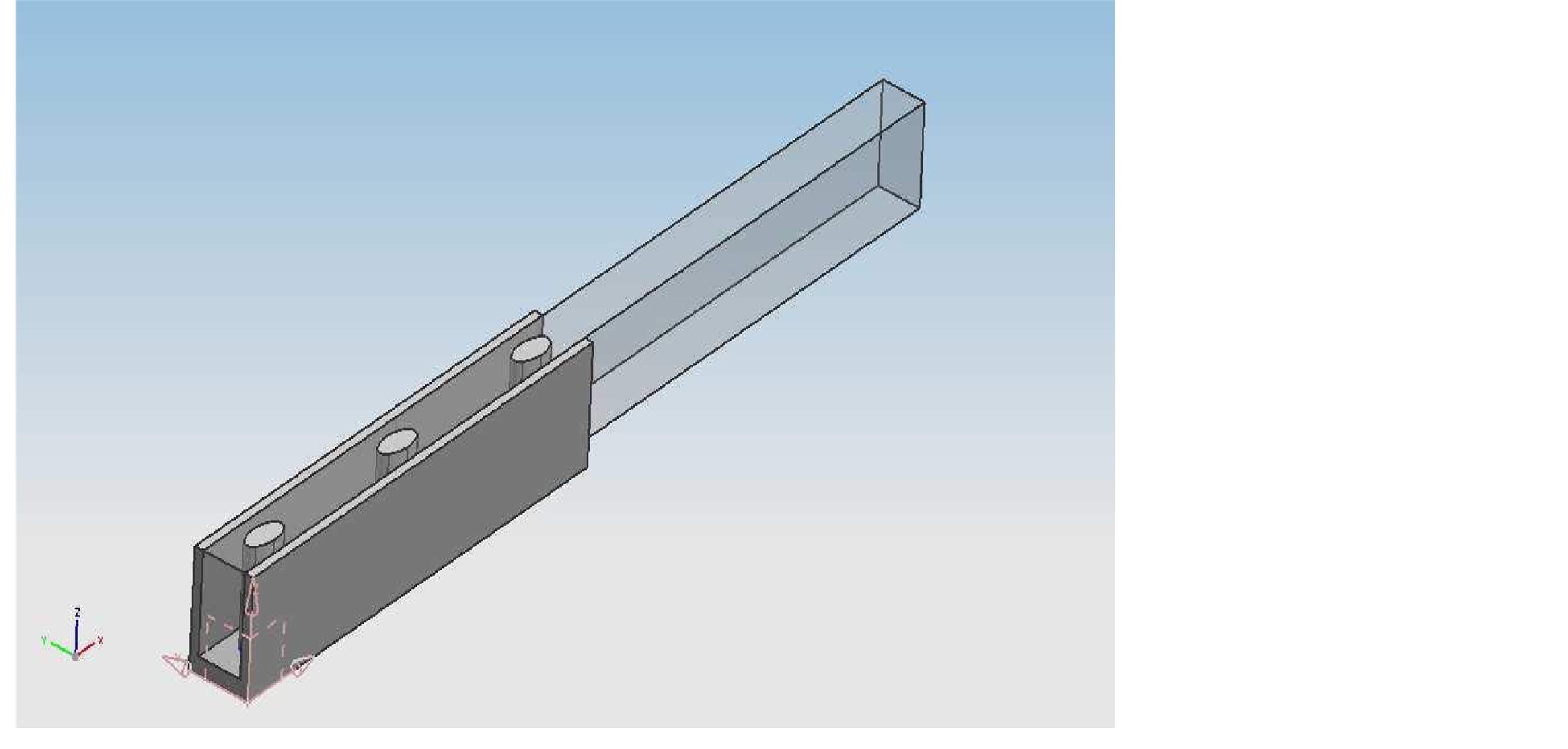
Figure 1: Plate-fin heat sink model
In CFD equations for heat transfer and fluid flow, the mass, momentum, and energy saving concepts are applied. Fluent software is used to decipher these equations. The algorithm that regulates fluid flow is created using physics’ conservation rules. Yu et al work ‘s inspired the dimensions of the measured surface heat sink. Figures 1, 2, 3, and 4 show the architecture of a plate fin heat sink and an elliptical pin-fin heat sink.
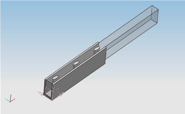
Fig. 2 illustrates the elliptical pin-fin model of 1.5. A heat dissipation device
Model 2.0 elliptical pin-fin is shown in Fig.3. A heat sinks
In the analysis, the flow is assumed to be three-dimensional, turbulence-free, steady and incompressible, the crimped fin study does not account for buoyancy or radiation heat transfer. All thermodynamic properties are considered to remain constant, such as (P-V-T).The air flow properties are described using the K ε turbulence model. The equations for momentum, energy and continuity are stated below.
A model of a 2.5 elliptical pin-fin is seen in Figure 4. Thermostat
Table-1 contains a list of geometrical parameters. Modeled after a novel elliptical pin-fin radiator, Periodic geometry is put to good use. The elliptical pins and periodic wall are used to transmit heat. The interior of the fin, i.e., the base of the fin, is where heat moves. Table 1 and Table 2 show the heat sink and elliptical pin fin specifications.
Table 1: Parameters of the heat sink’s geometry
| Length of fins (mm) | Height of fins (mm) | Number of fins (mm) | Thickness of fins (mm) | Fin distancing (mm) |
| 50 | 11 | 20 | 1.5 | 6 |
Elliptical Dimensions in Table 2 A heat sink with pin-fin fins
| simulation | Axis major (mm) | Axis minor (mm) |
| 1.5 pin fin simulation | 4 | 1.5 |
| 2 pin fin simulation | 4 | 2.0 |
| 2.5 pin fin simulation | 4 | 2.5 |
There, the heat being generated per unit volume of the heat sink is denoted by q, while the thermal conductivity is denoted by s.
Only one flow path is examined because of the heat sinks’ periodic shape. As may be seen in Table 3, we’ve used a variety of computational techniques. Aluminum is commonly used for heat sinks. The bottom layer of the computational domain has a constant rate of heat transfer of 10W and three distinct speeds (6.5, 9.5, and 12.5m/s). due to the low heating and the flow being considered 3-Dimensional incompressible steady turbulent, the air properties remain constant. The effect of radiation is not taken into account at all.
Discussion and Results.
A three-dimensional model is used to investigate the flow and conjugate heat transfer in a heat sink for electronic applications. We used FLUENT to perform a series of computational models to see how heat sink surface Nusselt figures and temperature distributions affect heat transfer coefficients and total heat transfer efficiency. The theoretical findings and actual data on the thermal resistances and differential pressure of the PFHS from the Yue-Tzu Yang, Huan-Sen Peng study [7] are shown in Figures 3.1-a and 3.2-b.
Result of Experiment and Simulation-
The heat sink’s thermal resistance, Rth, may be calculated using-
Rth ” (7)
Q
The temperature differential between the peak temperature at the base of the fin and the surrounding air is denoted by the letter T, and Q is the power used to dissipate heat at the base of the fins. Aluminum heat sinks with a thermal conductivity of 202 W/m are utilized in combination with a working fluid that has the same qualities as ambient air at 294 K. (m-K). In comparison to pressure drop, experimental data and thermal resistance have changed.

Wind velocity (m/s)
In the PFHS experiments and simulations, the relationship between the Nusselt Number and wind speeds is seen in Figure 5.
Figure 5 depicts the results of experimental and computer simulations for the PFHS Nusselt number. There is an increase in the size of dissimilar, yet in a comparable way.

Wind velocity (m/S)
The findings of the PFHS’s experiments and simulations are shown in Figure 6: The link between wind speed and thermal resistance.
Experimental and modeling results demonstrate that the thermal resistance of PFHS is constant (see fig. 6 above), although in a similar fashion.
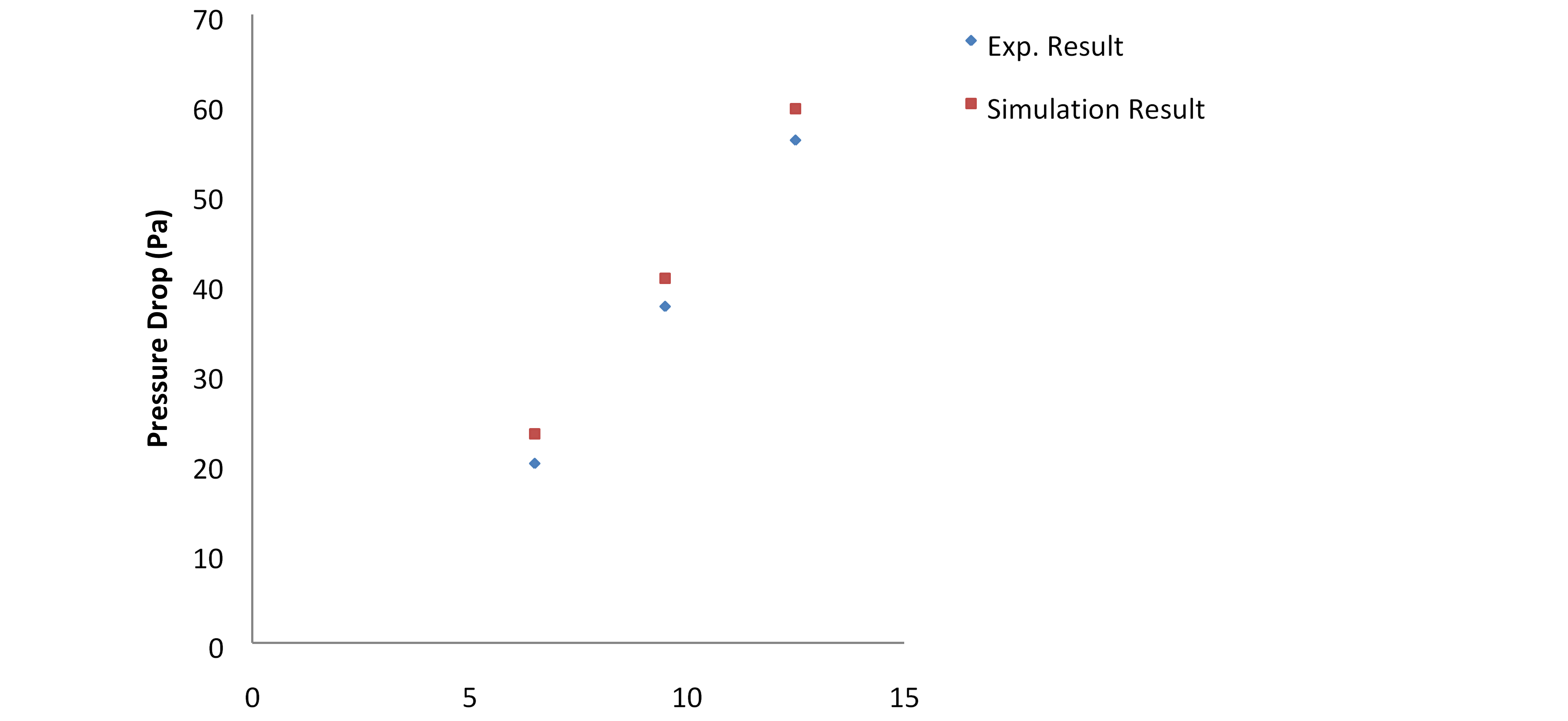
Fig.7: Experimental and computational data for the PFHS of pressure drop against wind velocities.
Figure 7 Depicts the results of PFHS pressure drop experiments and simulations. The outcomes are slightly better than expected.
The deviation is nearly consistent when compared to experimental values.
Performance compression between PFHS and EPFHS

Wind velocity (m/s)
Different Fin Profiles of Elliptical Pins Affect Thermal Resistance
Thermal resistance changes for various elliptical pin fin profiles are shown in Fig.8.
There is a consistent variance in both the experimental results of PFHS and the simulation results of various fin profiles of elliptical pins. As the wind speed rises (6.5, 9.5, and 12.5 m/s), the thermal resistance decreases.

Wind velocity (m/s)
Elliptical pins with various fin profiles exhibit different Nusselt number variations (Fig. 9).
Figure 9 shows one example of this.
varied elliptical pin fin profiles and their Nusselt number variations
The PFHS testing results (7) and the simulation results of various elliptical pin fin profiles show a constant deviance. As the wind speed rises from 6.5 to 12.5 m/s, the Nusselt number increases. In terms of experimental outcomes, this is an even more promising one. Variations in Elliptical Pin Pressure Drop Due to Fin Profile Variations in Figure 10.

Wind velocity (m/s)
A consistent deviance in the elliptical pin heat sink can be shown in Figure 10, which compares the plate fin findings (7) from PFHS with simulation results for various elliptical pin fin profiles. However, the experimental results are similar. This figure illustrates the rise in pressure drop that occurs when the amount of (6.5, 9.5, and 12.5 mph)
Wind velocity (m/s)
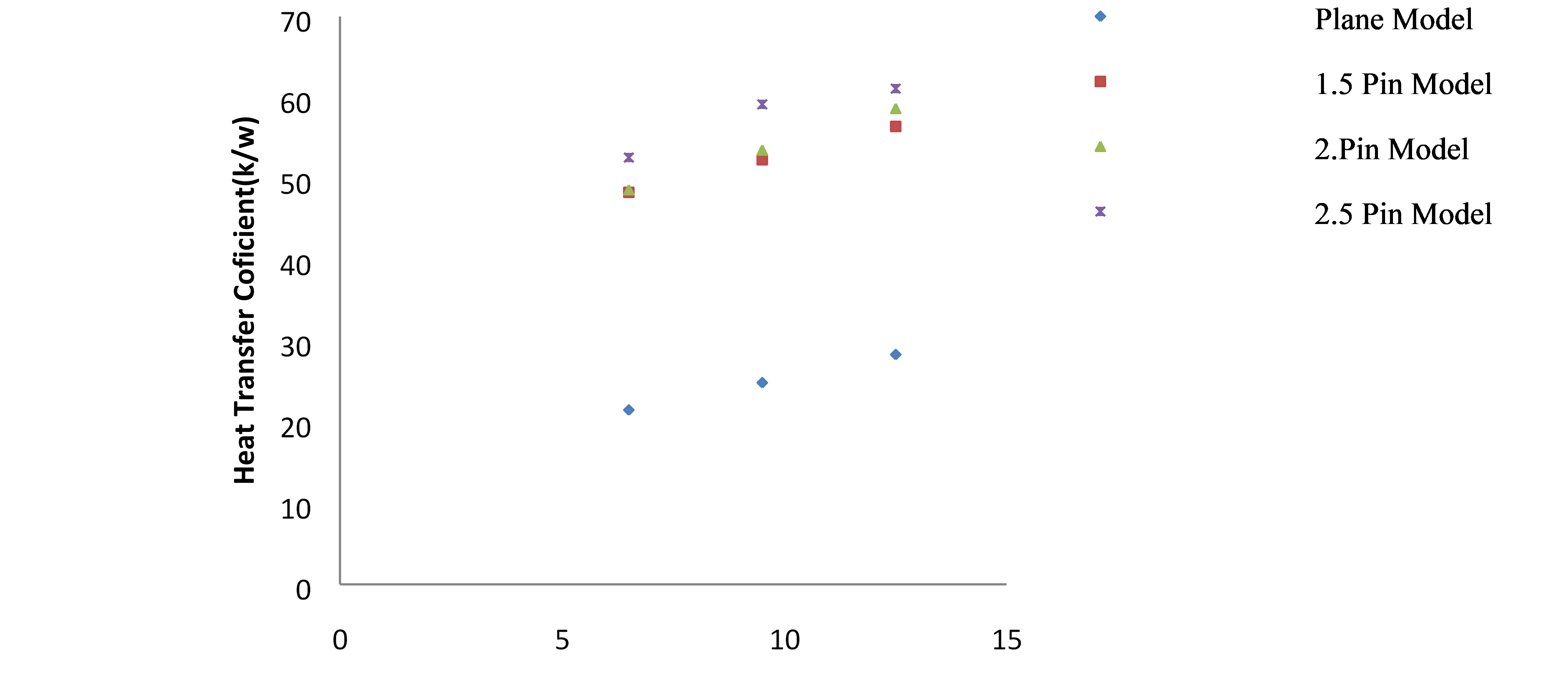
In Fig.11, the heat transfer coefficient of an elliptical pin is shown to vary depending on the fin’s profile.
Figure 11 depicts increases in boundary layer thickness, demonstrating that when wind speed increases, the coefficient of heat transfer also rises along the channel length. Due to the fact that the heating output is homogeneous throughout the bottom of the base of the fins, EPFHS has a lower thermal resistance than PFHS. Regardless, CPU heating is always centered on the fin base in a real-world engineering approach. When it comes to cooling, elliptical pin fin heat sinks can be used in a variety of ways, depending on the application.
ANSYS FLUENT has a temperature range constraint for stability concerns. The ceiling and floor temperatures are included to help stabilize computations by ensuring that the temperature stays within established boundaries in real life. A temperature above these limitations can sometimes be reached by intermediate solutions of the equations for which property definitions and the like are not properly defined. Your problem’s normal temperature range is maintained by using these temperature limitations. If the ANSYS FLUENT calculation predicts that the temperature will rise above the maximum limit, the previously saved temperature values will be modified “The maximum value has been “locked” in place. The temperature ceiling is set at 5000 K by default. Temperature readings are discarded if the ANSYS FLUENT model predicts a temperature below the minimum threshold “”strung” to this minimal value.” The minimum temperature is set by default to 1 K.
Using the Solution Limits dialog box, you can increase the Maximum Temperature to 5000 K if you expect the temperature in your domain to exceed that level.
Predictions of heat transfer qualities are critical in many engineering simulations, if not more critical, than the flow field. Some examples of these scenarios are the simulation of heat exchangers (HVAC), combustion/burners (electrical cooling), as well as many others. In these applications, heat transfer at interfaces, both within as well as between fluid and solid realms, is a prevalent issue. The three modes of heat transfer that ANSYS CFD can solve are convection, conduction, and radiation. The physics that are included in a CFD model determine its efficiency. Despite its computational expense, radiation is an important heat transmission strategy for bodies that radiate heat to cooler surrounding bodies or lower ambient temperatures (since radiative heat transfer scales with Temperature4).
The convection heat of a finned heat exchanger is seen here. Air flows from left to right, as indicated by the arrows in the diagram.
In this image, heat from a finned heat exchanger can be seen converting away. The illustration’s streamlining portrays air moving from left to right. Fin size, shape, and number can all be optimized using CFD and Design Optimization methodologies. We can use conjugate heat transfer (CHT) whenever we want to study the heat transfer between two nearby domains. Solid or fluid domains can exist in these spaces. One example of forced or natural convective cooling is a heat-sink coupled to a heat-generating dynamic electrical component.
It is also possible to study heat transfer between solid-solid and fluid-fluid domains. Solid-solid interfaces are employed when two solid objects are in close contact to one another and heat is exchanged. Even though a fluid-fluid CHT setup may appear to be unphysical, in some cases, such as a co-flow heat exchanger with two fluids surrounded by a thin wall, it’s a plausible assumption.
Heat transfer across the partition wall can be considered to be insignificant in this instance, as it is not necessary to specify mention the wall thickness when calculating heat transmission. In all of the cases below, the thermal impedance can be applied to the interface in ANSYS CFD. Thermal coatings (which are extensively used in electronics) or poorly matched surfaces between nearby items can be depicted using such resistances (to comprehend the tolerance for shoddy connections). In this cross-section in the stream-normal plane, finned heat exchangers can be seen. At the bottom boundary condition, heat enters the system and is disbursed into the surrounding air.
This graphic depicts a cross-section of the heat exchanger’s stream-normal plane. Electronic components on the base generate heat that goes into the heat sink and into the surrounding air via the heat sink fins and the airflow around it. This heat transfer relies on the boundary layer, which necessitates the use of a suitable near-wall mesh.
It’s critical to use boundary conditions that adequately reflect the real environment while running CHT simulations. ANSYS CFD’s thermal boundary conditions can be adjusted using UDFs or CCL expressions, enabling for the simulation of any heat transfer scenario.
Because the thermal boundary layer must be precisely resolved, the wall-adjacent mesh size is critical for accurate CHT results. We can apply a similar strategy to settle the viscous boundary layer (for correct flow separation, pressure drop) while generating high-aspect ratio prism or hexa elements stacking in the wall-normal direction to solve the thermal boundary layer (for example) (protruding into the fluid domain). In the solid domain, however, because convection does not exist, a coarser, more uniform mesh can be used instead.
Conjugate Heat Transfer simulation with ANSYS CFD can be used in a wide range of industries, including electronics, construction, and power generation. Innovative designers and manufacturers all over the world are using simulation-driven product development (SDPD) methods that use CHT simulations. If heat transfer is a concern in your design, reach out to LEAP right away.
Conclusions.
The primary axis of an elliptical pin fin is changed in this paper in order to improve its heat transmission performance. Three minor-axis diameters (1.5mm, 2.0mm, and 2.5mm) and three heat input speeds (6.5m/s, 9.5m/s, and 12.5m/s) were used in the simulations. The heat resistance of the elliptical pin fin with a minor axis of 2.5mm, 2mm minor axis, and lastly 1.5mm minor axis is the lowest. At 1.5mm minor axis, or 145Pa, the elliptical pin fin has the least pressure drop. The next lowest pressure drop occurs at 2mm minor axis, or 180Pa, followed by 2.5mm minor axis, or 280Pa. At all velocities, the 2mm minor axis elliptical pin fin has greater pressure drop and heat resistance than the 2.5mm and 1.5mm equivalents, according to the data shown above.
References.
S. Lee, Optimum Design and Selection of Heat Sinks, Proceedings of 11th IEEE Semi- Thermal Symposium, pp. 48-54, 1995.
Sergent, J. and Krum, A., Thermal Management Handbook for Electronic Assemblies, First Edition, McGraw-Hill, 1998.
Patankar SV. Numerical Heat Transfer and Fluid Flow. New York: McGraw-Hill; 1980.CFD-Wiki http://www.cfdonline.com/Wiki/Main Page
Manay E., Sahin B., Yilmaz M., Gelis K, “Thermal Performance Analysis of Nanofluidsin Micro channel Heat Sinks”, World Academy of Science, Engineering and Technology 67 2012.
N. Nagarani, “Experimental Heat Transfer Analysis on Annular Elliptical Fins and Comparison with Circular Fins”, European Journal of Scientific Research, ISSN 1450-216X Vol.73 No.2 (2012), pp. 143-156.
Hung-Yi Li a, Go-Long Tsai et al, “Measurement of thermal and hydraulic performance of a plate-fin heat sink with a shield”, Experimental Thermal and Fluid Science 42 (2012) 71–78.
Yue-Tzu Yang, Huan-SenPeng, “Investigation of planted pin fins for heat transfer enhancement in plate fin heat sink”, Microelectronics Reliability 49 (2009) 163–169.
Xiaoling Yu, JianmeiFeng, “Development of a plate-pin fin heat sink and its performance comparisons with a plate fin heat sink”, Applied Thermal Engineering 25 (2005) 173–182
 write
write